Course Index
Select a section to jump straight there. Quiz questions rotate on every visit — one attempt per question, results at the end of the page.
This short course focuses on the design and construction of timber decks in a South African context. It is aimed at architects, engineers, other built environment professionals and DIY enthusiasts in South Africa who want to explore the use of wood in residential decks. We hope you will find this course helpful and practical.
How to complete this course
The course is open access and the content is available to anyone with internet access. This course should be completed in the sequence of the numbered sections. We make use of four components in our course (a) sections with text and illustrations, (b) video clips to explain some of the concepts, (c) a short online quiz after each section to test your acquired knowledge and (d) a test, available to learners who wish to obtain a certificate of completion. Please contact us at info@thewoodapp.com with the short course name to complete this test.
To make the course accessible to most people, we’ve tried to limit the time needed to complete it (an estimated 2.5 hours). This course will give you an overview of selected building materials impact and the environment, and design strategies to incorporate timber in a sustainable way. For in-depth knowledge on some topics you might require input from other sources such as national standards, material suppliers, selected textbooks, articles, etc.
If you have any questions or suggestions, please contact us at info@thewoodapp.com.
Timber Deck Building Short Course Video
Disclaimer
In the compilation of this module, free use was made of published information such as text, figures, drawings, tables, graphs, etc. As the use of such material is subject to copyright considerations, and the suitability and relevance of this content is in the process of being assessed, the content of this module is only reserved for personal use and the purpose intended. To adhere to copyright regulations, any publication of the module or parts thereof considered, is subject to obtaining the necessary copyright agreement from the publishers by the author. Photographs taken and figures, drawings, tables and graphs generated by the author, are subject to copyright as well.
Whilst all and the utmost care has been taken to ensure the accuracy of the information contained in this module, no warranty can be given regarding the use, suitability, validity, accuracy, completeness or reliability of the information, including any opinion or advice.
Overview
1.1 The design process
Although design and construction of a timber deck can be an uncomplicated process, some basic principles need to be applied. Structural integrity, durability and aesthetic appeal are the three important principles that should guide most decisions in this process.
Legally it is important to understand that local authority approval is needed for a deck structure. There is some controversy regarding the submission of deck plans as it may be seen as “minor building work”. According to SANS 10400-A section 13: “…. (g) the erection of any other building where the nature of the erection is such that in the opinion of the building control officer it is not necessary for the applicant to submit, with his application, plans prepared in full conformity with these Regulations.”It is best to contact the local authority in your district for clarification on this matter. However, for liability issues it is strongly advised to have an engineered approved deck plan submitted. An engineer would typically use SANS 10082 Timber frame buildings, SANS 10163-1 The structural use of timber – Part 1: Limit-states design to produce a rational design, and SANS 10043 The installation of wood and laminate flooring, which includes a clause related to solid wood decking.
1.2 Timber deck types
Deck designs normally starts with some research, deciding on a style and basic dimensions, with the aim to be fit for use and aesthetically pleasing. Classification of decks can be wide, but here are some basic style options, viz: Loose standing vs attached; low level vs elevated; rectangular vs curved; covered vs open; and access deck/jetties/boardwalks. Combinations of these options can result in innumerable design choices.


1.3 The MUST KNOW aspects of timber deck in design
Timber is a versatile, light and strong building material and has been used successfully for centuries. Conversely, there are also instances of disaster due to timber failing as a result of deterioration or being under excessive stress. It is thus important to know the application and limitation of this building product, especially related to durability.
Moisture and Wood
Most timber rot away naturally when left in nature. Using wood as structural members for longer periods, therefore, usually needs intervention. Biological agents that are responsible for wood decay thrive in higher moisture content environments. Correct detailing of designs can prevent moisture traps and so prolong lifespan. When application necessitates high moisture environments, like a planted pole or exposed substructures, then chemical pressure preservation of timber is specified and required (see SANS 10005). Note that different applications deal with different levels or hazard classes. Make sure to use SANS approved treated timber that bears identification markings.A brief summary of the treatment hazard classes can be seen below. For more detailed descriptions, see SANS 10005:
H2 – Low hazard applications: Internal structural applications (i.e. roof trusses and timber frame walls)H3 – Moderate hazard applications: Exterior above ground applications (e.g. exposed decks)H4 – High hazard applications: In-ground contact applications (e.g. planted poles)H5 – Very high hazard applications: In fresh water and heavy wet soil applications (e.g. wetland pilings)H6 – Extremely high hazard applications: Marine applications (e.g. sea pilings)
Weathering
Intermittent wet and dry climate resulting in timber expansion and shrinkage causing surface checking can lead to accelerated degrading, especially in horizontal members like decking boards. Certain wood species are more resistant to this defect than others, therefore the selection of decking boards is important. Sealing and maintenance of the surface coatings can also prolong deck board lifespan.
1.4 Timber Grades
The use of SANS structurally graded and preservative treated (exterior decks) timber is important to conform to building standards and to satisfy engineered designs. The process to grade and produce structural timber with guaranteed minimum characteristic load stresses, is covered in another online course.
Red marks of the grade spaced along the length of the timber members indicate grade stresses, where the most common grade is S5.
1.5 Selecting a Building Contractor
It is highly recommended that you work with an experienced timber deck design team and with contractors that can follow or exceed SANS 10082. Select a contractor based on previous project experience and results, or visit SAITB or your local architect for recommendations.
1.6 Quiz 1
Quiz 1 — Overview
Foundations
All structures need sturdy foundations to transfer loads from the structure to the earth. Timber, being a lightweight material, requires smaller foundations compared to brick-and-mortar structures. Decks require small (but necessary) foundations to bed the structure and keeping it from displacement over its lifespan. There are some effective types that will be discussed in this section. Foundation placement is very important as this will guide the entire structural alignment and care must be taken to accurately set it out.

2.1 Setting Out of the Deck
After clearing the site, it is of utmost importance to spend time and effort to make sure that the deck is set out accurately and that a reference line is identified that can be used throughout the entire construction. A reference line can be used to show the final finished height and also as a squareness guide.

Determining finished floor height
Decks joining onto existing buildings must be lower than the finished floor level of the building to reduce water ingress possibility as well as preventing door opening jams on the deck (see Figure 5). Planning must be ‘top- down’ starting with the reference deck board height and calculating back to foundation level. The existing area is seldom level, demanding adaption on post lengths. Spirit, dumpy and pipe levels all work well, just make sure they are calibrated first.

Ensuring squareness
Free standing decks are less complicated than decks attached to buildings. Some buildings are not square, giving rise to a non-square deck that will show on decking boards. Deck boards normally run perpendicular to the entrance and parallel to the longer length of the deck. Should a deck not be square, it becomes very challenging to lay parallel boards. Pythagoras’s theory can be effectively implemented to assist in setting out square lines accurately. The 3-4-5 length triangle will create a square angle (see Figure 6).

To ensure that a square or rectangular deck is properly square, the diagonals should be equal length (A=B, see Figure 7). This is a quick and practical method to use and only requires a long length measuring tape.


2.2 Foundation Types
There are different types of foundations that can be used for a deck. Typically, a timber deck is built on a pole foundation that will be discussed in detail in this chapter.
Preservative treated timber poles are readily available in different lengths and diameters.
Table 1: Soft and Hardwood Available Pole Dimensions, Adapted from SANS 457-2 and SANS 457-3
| Type | Sizes (top end diameter groups in mm) | Length (m) |
| Softwood | 50-79, 80-99, 100-119, 120-139, 140-159, 160- 179, 180-199 | 1.2, 1.5, 1.8, 2.1, 2.4, 2.7, 3.0, 3.3, 3.6, 3.9, 4.2, 4.5, 4.8, 5.4, 6.0, 6.6, 7.2, 7.8, 8.4, 9.0, 9.6, 10.2, 10.8, 11.4, 12.0 |
| Hardwood | 50-74, 75-99, 100-124, 125- 149, 150- 174, 175- 199 |
According to SANS 10082, the minimum pole diameter is 100 mm, or has a cross sectional area of 7 500 mm2. Popular pole sizes for use as foundation posts are between 120 and 180 mm. Longer posts require larger diameter poles. Small diameter post that are too long can cause deck instability. Consult a professional structural engineer if a structural analysis is required.
Hardwood and Softwood Poles
There should not be a large difference between hardwood and softwood poles and choice most probably boils down to personal preference and availability. But to highlight some differences and features, a discussion of both is needed. Hardwood poles (or gum poles as it is also known), is a collective name for poles produced from the Eucalyptus genus tree which is a hardwood or broadleaf. There are many species in this genus, initially imported from Australia, that are widely planted in South Africa for pulp and poles due to its adaption to our climate and extremely fast growth. The density and strength vary between different species but is generally higher than softwood species such as the pines used in South Africa. The bark is stripped off in the plantation, leaving a natural smooth surface with small knot holes. Gum poles may exhibit high growth stresses and tend to split and crack on the ends. Anti-splitting plates are hammered in to prevent reject size cracks forming. The majority of gum poles produced in SA are however E. grandis or E. grandis hybrids.
Pine is also a collective name for commercially planted softwood species (needles instead of leaves) from the genus Pinus in South Africa. Pines have less growth stresses and are much less prone to splitting, although they are characterised by larger knots and tend to be more variable in shape (ovality, taper, crook, and sweep). Pine logs are debarked with a machine leaving a slightly rougher surface but uniformly tapered pole. In the case of Pine, only P. radiata, P. canariensis and P. pinaster are presently allowed for SANS 457-2 load bearing poles. Both gum and pine poles are graded according to various attributes to be classified as either “building and fencing” (SANS 457-2 and SANS 457-3) or “telephone and transmission” poles (SANS 753 and SANS 754). Both of these classifications can be used for deck posts.
There are different types of wood preservative chemicals used to pressure treat timber, but mainly CCA (waterborne copper chrome arsenic solution) and creosote are used for H4 and higher hazard class applications. CCA poles can be identified by a greenish colour while creosote poles are brown/black in colour due to the copper. There should not be a difference in durability between these different chemical preservatives, however some important differences need to be noticed.
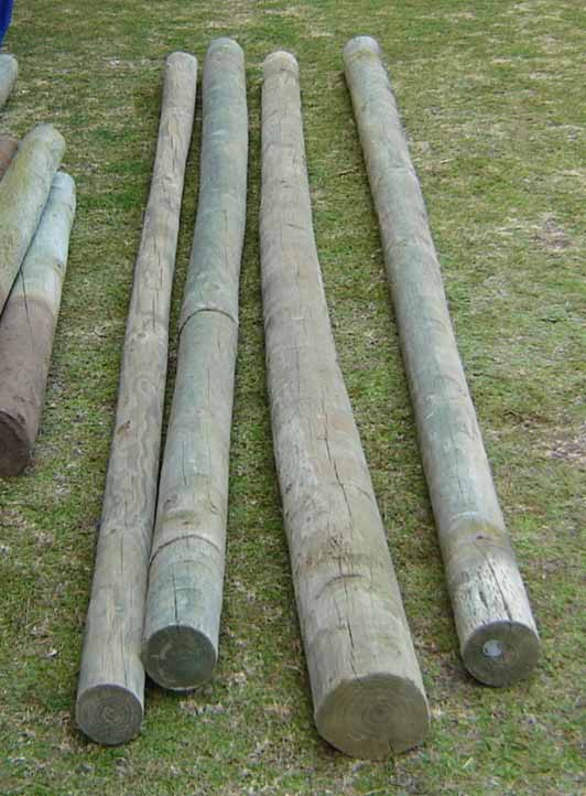

Taper and Rounded/Cylindrical Poles
There are two types of pine pole ‘forms’ on the market, viz. machined tapered (debarked) and cylindrically turned poles. Gum poles are available only in a natural taper form. Tapered poles have been debarked to remove bark and some surface defects. While rounded poles have been shaped into a cylinder so that top and bottom ends have the same diameter, tapered poles have the trees’ natural taper. Using cylindrical poles makes it easier to erect, gives a cleaner line in the design and exhibits a smoother surface. However, in the shaping process significant fibres on the base end of the pole is shaven off, not only reducing the strength but also increasing the risk for uneven sapwood thickness. Cylindrically turned poles do not comply with SANS 457-2 and are not regarded as strength graded poles. They can, however, be used provided that the design used in the construction is approved by a competent and qualified engineer. Sapwood is the outer wood that can receive a wood preservative chemical. According to SANS 1288, the minimum sapwood required for pine poles (tapered or cylindrically turned) is 20 mm, and for gum poles 13 mm for the poles to comply to H4 exposure class applications. In short, a cylindrical pole may be more at risk for decay than a tapered pole, even if treated by a reputable treatment plant, if the minimum required sapwood in some of the poles do not comply.
Pole Planting Techniques
There are a few correct pole planting techniques that will be discussed in this chapter. Incorrect planting techniques can cause premature degrading caused by water traps, and in return decreases durability. Planting a pole must be done correctly to stabilise the deck by sufficient anchoring.
Collar Pole Plant Technique
This is a very common technique to fix a pole and add structural stability. After a 300 mm diameter x 600 mm deep hole is dug in the soil, the pole is placed in the centre of the hole and a low strength concrete mix (10 – 15 mPa) is poured around the pole. Make sure the pole is plumb and supported in the correct position with three stakes. Skew planted poles can be aesthetically unacceptable and can cause instability as well. Choose two faces at right angles to each other that can be used as reference for plumbness in case of tapered poles. Stakes can be removed after a few days to work on the pole. Make sure that no poured concrete is under the pole when planting. This will set in a cup shape that will trap water and lead to pole degrade. To prevent this, a first layer of compacted back fill can be used before pouring the collar.

Footing Pole Planting Technique
Instead of using concrete, backfilling material is compacted around the pole that stands on a precast concrete footing. Correct size footing will decrease pole pressure and sinking effect, increasing deck stability. This is a popular method when deck stability is not a major issue, i.e. low deck. Place a concrete footing in the base of a 600 mm deep hole. The width will depend on the footing size; the area of the concrete footing can be 300 x 300 mm to 600 x 600 mm and concrete can be 50 mm thick. This footing must be completely set and dry before the pole is planted. Position the pole in a plumb upright position. Back fill with compactable material with low clay content – G7 materials work very well. Only fill a 150 mm layer after the previous layer was properly compacted. Fill and compact layers until level with the surface. Correct backfilling material and technique will increase deck stability significantly. For more information, go to https://sawpa.co.za/how-to-plant-a-pole/


There are several other kinds of foundation types apart from poles that can be used. A number of them are described in Figures 15 to 18.


Steel Post Brackets
These are galvanised steel brackets that clamp a square/rectangular post above ground while part of the support itself is fixed in a concrete base (Figures 15 and 16). There are many different designs, from simple to adjustable systems. In all of them the post is clamped/bolted on the bracket and the bracket fixed to a concrete base. Using elevated post clamp brackets for square posts will increase deck durability. Deck stability will be less than that of a planted pole system, as the bracket pole connection can pivot unlike a planted pole.

Concrete Footing
Precast concrete blocks with post and joist recesses make a quick and simple foundation for low level decks or temporary decks. This has similar advantages than the steel post support that was discussed, but added the fact that no other concrete foundation is needed reducing the installation time even more.
Brick or Concrete Piers
Non-timber post is possible by either precast concrete piers or masonry plinths. This building method specification can be found in SANS 10400-J. Some examples are shown below:

Bracing of Posts
Post for 1st level or elevated decks must be braced to increase deck stability. The most effective bracing is a timber member connected at the top of the corner post connecting to the foot of the adjacent post, aiming to create a 450 angle. This should be done on the deck face and side.
Should the deck be fixed to an existing building and the diagonal post bracing be inappropriate, then a diagonal bracing element under the deck itself can be inserted. Bracing a deck effectively will increase stability. There is a huge difference in the load that a high, loose standing deck with bracing can support compared to an unbraced deck. When bracing is added a deck can support roughly 8 times higher loads before poles will buckle compared to an unbraced deck.

2.3 Quiz 2
Quiz 2 — Foundations
Superstructure
3.1 Bearers / Beams
All sawn timber used in the substructure for deck building must be treated to at least H3 (above ground outdoor). Poorly or untreated timber will lead to reduced durability and most likely premature failure.


Bearers (beams) are fixed to the poles and span to the next support and create a level beam onto which the joist rests. The size of the bearer is dependent on the load and the span distance. Load is influenced by self-weight and live loads while the span is influenced by post support distance. Longer span bearers have less post supports, but need to be of larger size, especially in depth. Typical bearer sizes are 228 mm x 50 mm and 228 mm x 76 mm and it is of the largest dimension structural timber that sawmills can produce. Typical span distance of bearers is between 1.8 m and 3 m. Should longer spans be needed, H3 treated laminated beams can be used. Spanning out of specification of bearer size will cause deck instability. Bearer spacing is determined by the span of the joist. Typical 152 x 50 m S5 joist can span up to 3.5 m.
Fixing of bearer to post
The most popular method of fixing a bearer to a post is bolting on a seated post. The post is notched 10 mm deep to seat part of the bearer. Hot creosote brush-on treatment is applied to notched area. Two 10 or 12 mm bolts with oversized washers is used to clamp the two members together. Coach screws (lag screws) may also be used instead of bolts. Nailing of bearers to post is not acceptable as the nails will loosen over time causing deck instability. The bearer is fixed to each post making sure it is level. Poorly levelled bearers will lead to unsightly unlevelled deck surface influencing aesthetics negatively. This is also a good time to cut the timber post to correct level, slightly below the bearer angling the cut away from the bearer, which is both practical and allows for water runoff. Apply a suitable preservative (e.g. hot creosote or a registered remedial brush on preservative) to remedially treat the exposed untreated end grain to increase deck post durability. Lengthening of bearers is done close to the post but not on the post, using a scarf joint and fixing gang nail plates both sides of the joint. Butt jointing of bearer in a post can become instable.


3.2 Joists
Joists are members that span between bearers and provide fixing for the decking boards. The span distance of the joists is listed in the table from SANS 10400. The smallest joist is 38 mm x 152 mm and as S5 grade, it will also have the shortest span (2.7 m). Note that should the joists be spaced closer to each other (400 mm), the span can increase (3.1 m). The largest and strongest joist, 76 mm x 228 mm S7, can span to 6.5 m at 400 mm spacing.
Although 38 mm thickness joists are available, a 50 mm thickness joist will provide a wider fixing surface for the decking boards, making it a better choice. Some joists are more readily available in H3 preservation classification than others.
The spacing of a joist is influenced by the span capability of the decking board. The acceptable rule of thumb of maximum deck board span is 20 x deck board thickness. An example is of the popular 20 mm thick decking board which will span 400 mm – which will be the spacing of the joists.
Joists can either be fixed on top of or inside the bearer. Fixing them on top is simple and effective using the skew nailing technique (see Figure 26). Joists can be joined by overlapping and nailing on a bearer and should not be butt jointed on a bearer.
To construct a low flat deck, the joists can be connected inside the bearer with a truss hanger. This galvanised steel bracket is available in 38 mm, 50 mm and 76 mm widths and various depths. Fixing is done with coach/lag screws and clout nails. The joists length needs more accurate cutting as the tolerance of this joist is much smaller (1 mm) for acceptable installation. Timber cleats can also be used to support the joist inside the bearer should the bearer be deeper than the joist. The cleat is fixed to the bearer at each joist interval with a coach screw. Levelling a deck can be done on the bearers as well as on the joist, making it possible to result in a well levelled platform.
Note – All cross-cut ends and notched areas must be remedially treated with a suitable brush-on preservative to ensure that any exposed untreated core is protected.


Table 2: Maximum Span of S5 Pine Joists for Domestic Application (SANS 10400 – J, 2016)
| Width (mm) | Depth (mm) | Maximum joist span (m) at set spacings | |
| 450mm | 600mm | ||
| 38 | 152 | 3.1 | 2.7 |
| 228 | 4.6 | 4.0 | |
| 50 | 152 | 3.5 | 3.1 |
| 228 | 5.3 | 4.6 | |
| 76 | 228 | 6.0 | 5.5 |
Joistless framing can be accomplished by using bearers only. This is a practical system if the decking boards are thick and can span far enough to reach the opposite bearer. A typical example is a narrow deck or boardwalk where a 50 mm thick deck board can span 1000 mm and design features prefer to have deck boards perpendicular to the pathway.


Bridging of Joists
To increase floor stability, bridging of joists can be implemented by joining adjacent joists to each other. This is especially done on slender joists that tend to buckle under strain. Bridging not only stiffens the joist but also helps with load sharing to adjacent joists decreasing deck bounce by increasing stability. Block bridging is effective and relatively simple to install.

3.3 Quiz 3
Quiz 3 — Superstructure
Decking Boards
4.1 Types of Decking Board
The choice of decking board can influence durability as well as the aesthetics of the deck. Decking boards receive the harshest weather exposure of all members. Sun exposure on the surface, water accumulation and foot traffic can quickly lead to deterioration, degrading the appearance and performance.
There are many different types of decking board – from traditional hard -and softwoods to plastic and wood-plastic composites. Timber is a natural resource exhibiting high variability in board products. Some of the timber characteristics can become defect if used as a decking board.
Selected species of softwoods and hardwoods can be used for decking. Softwoods are generally lighter, easier to machine, accept fasteners like screws and nails with more ease and show less expansion, shrinkage and end splits. However, softwoods are usually not as strong and hard, making it prone to indentation. In most instances softwoods are not as durable as hardwoods, but can mostly be suitably pressure treated with preservative chemicals. A common pine deck board size is 22 mm x 102 mm and lengths in 300 m increments from 1.8 to 6.6 m. Longer lengths will most probably consist of several pieces finger-jointed together. The finger joint itself should be stronger than the weakest allowable defect on the plank if correct procedures and glues were used (SANS 10096). Untreated or incorrectly treated softwood decking boards will show decay within a year or two. Pressure treatment with preservatives to at least H3 hazard class level will greatly increase the durability of softwood deck boards.

Most hardwood decking boards are imported and more costly than local grown preservative treated pine, but may have some added advantages. Hardwood exhibits higher compression strength in general, making it less prone to surface damage and indentation. In general, hardwoods are more durable (there are exceptions) and do not require pressure treatment (or cannot be pressure treated as easily as most softwoods). Due to higher densities of hardwoods, installation can be more challenging as screwing, drilling, sawing and shaping is more difficult than with softwoods. Splitting on ends and surface checks is also more prevalent. Imported hardwood thickness is generally 19 mm and widths are between 90 mm and 140 mm, while lengths are usually limited to 3 m.
Users of hardwoods should make sure that the wood is sourced from a sustainable supply. Hardwoods often originate from tropical forests, a biome that is very sensitive to exploitation and is much less robust than temperate forests. Using tropical hardwoods sourced from certified suppliers (i.e. FSC certified) is the responsible option.
It is very important to realize that only the heartwood or core section of untreated wood can be durable if it is from a hardwood species rated as naturally durable. The sapwood, the section close to the bark, is non-durable for all species. For many hardwoods, the sapwood is of a lighter colour. These sections should be avoided for decking boards.

Popular imported hardwood species include:
Garapa: Apuleia leiocarpa from Brazil. Rot resistant but not insect resistant. Low splintering characteristics. Workability is moderate. Very popular in RSA.
Balau: Shorea laevis from Malaysia (same genus as meranti.) Durability is variable, hard timber with interlocking grain, difficult to machine. Splintering can occur on unsealed surfaces.
Ipe: Handroanthus spp. From central Americas. Very dense timber (sink in water). Very durable to insect and rot and mechanical wear. Difficult to machine.
Locally grown hardwoods include:
Gum: Eucalyptus species introduced from Australia, but locally grown. Of the many different species there are some that make good decking boards. E. diversicolor (Karri) is rated as durable with moderate workability. E. cladocalyx (sugar gum) is very dense and exhibits high resistance to rot and insect attack. E. marginata (Jarrah) is known for its high compression strength and was often used for railway sleepers in RSA, and rated as very durable to rot and insect attack. E. saligna and E. grandis that are commonly available and sourced from local South African grown commercial gum plantations, are non-durable species.
Engineered wood-based products
Wood Plastic Composite (WPC) is basically wood flour glued together under pressure and extruded into decking boards. It is available in typical deck board dimensions and in different colours. A major advantage is the resistance to decay and insect attack. It is also splinter free and has negligible shrinkage/expansion and with no warp. The flip side is lower stiffness than wood that will need closer support (joist spacing), increasing substructure costs. UV is also known to degrade the board over time, causing sagging and sometimes failure. Composite decking is also known for high surface temperatures.

Reconstituted Bamboo
This is bamboo fibre which has been glued together with resin, forming a high density and rigid decking board with resistance to decay. It is very stable and has high strength. It has all the same advantages of WPC, adding to that high stiffness which makes it one of the preferred decking boards.
Profiling of decking boards
Boards are usually planed all round and corner rounded (profiled). The surface can be as is (smooth) or fluted/ribbed/reeded – these are terms used to describe multiple fine grooved surfaces. Some boards also have anti-cupping groove slots on the back side cut in. Boards with special face profiling, limit boards being installed only in one orientation. Smooth boards that have all four corners rounded has the advantage of being installed either way.
a. Fixing of decking boards
Boards can be nailed, screwed or clipped onto the joist with different types of fasteners that will be discussed in this section. Correct fastening techniques can greatly influence aesthetics as well as deck durability.
Nails are the most economical fastener system and has the lowest installation cost, making it an attractive option for low cost or temporary decks. Nails should generally be twice the length of the thickness of the deck board. Although wire nails will do the job, galvanised nails will last longer. Ring shank nails have larger withdrawal resistance and will “pop” less. Popping occurs when the nail lifts out of the joint due to timber shrinkage and expansion cycles as well as vibration from deck traffic. Nails’ heads can be driven flush to the board surface sealing the fastener hole successfully. However, nails in hardwoods need to be predrilled to 70% of nail shaft thickness, increasing installation costs. Driving nails is a skill and can result in a damaged board if not done properly. Repairing the deck in future can be difficult, and loosening a ring shank nailed board is very difficult.

Screws
Screwing is the most popular system used currently – and for good reason. Screws grip the board, pulling it against the joist and keeps it there, unlike nails that can “pop”. Battery operated drivers has revolutionised the timber joining industry making it possible to produce acceptable results with semiskilled operators. There are also many different screws on the market, some specifically designed for deck boards. “Chipboard” screws can work for low cost or temporary decks but best to avoid due to low corrosion resistance. Stainless steel screws are more expensive but will outlive the decking board. Stainless steel screws have very weak torsion resistance and inserting them must be done with care, doing predrilling and with a set torque on the driver. Twisting the head off while the screw is inserted halfway is a risk if not careful. Screws’ driver slots can vary from Pozi, Torx and Square. Torx design seems to be the preferred design for deck builders.
Note – Where copper-based preservative treated timber decking is used, care should be taken to use nails or screws that have the required corrosion resistance for the preservative type applied to the timber.

Clips (invisible fastening)
Newer technology on the market makes use of a hidden bracket system that clamps the decking boards onto the floor joist eliminating unsightly screws on the board face. These do not only add to the aesthetic value but also reduce the water cupping effect of screw holes. High moisture gives rise to higher probability of fungal decay setting in. It comes at a higher cost, longer installation time and requires a skilled installer. Grooves alongside the boards’ edges are also known to tear off in wood that tends to split. And hardwood with a tendency to cup or twist is not constrained enough by these clips.

4.3 Laying Out of Decking Boards
The deck boards are the visible feature of the deck and can be one of the most expensive elements. A good layout will maximize deck board usage, reduce wastage and enhance design. Precise deck board layout and accurate fixing detail can increase aesthetic value and increase deck board durability. Although there are many different design possibilities, the most acceptable is the board perpendicular to the entrance and parallel to the longest side in the case of a rectangular shaped deck. The ideal board length will run the entire length of the deck with no joints, giving it a clean look. Should boards be jointed, it is advisable to step/stagger the joints and not have all on one joist.

Nailing and screwing pattern is usually 2 x fasteners, spaced 20 mm from the edges fixed on every joist (see Figure 36). Heads should be flush to the surface. If it is too deep it will tear the fibre, making an unsightly connection and cause water catchment that will enhance fastener corrosion and decking board fungal activity leading to rot. If the head is too high it will cause poor connection and an uneven surface. Fastener’s line is guided by a chalk line that indicates joist centre. Fasteners must be driven-in perpendicularly to the face of the deck board. Butt joining of decking boards is on the joists’ centre. Careful installation is required as not to split the ends.
Gaps between boards are typically set at 3-5 mm to accommodate water drainage, even if the board has swollen. Larger gaps tend to feel uncomfortable on bare feet and smaller objects can drop through. In general, hardwoods with larger densities swell more than softwoods and need larger gaps. So do wider boards need larger gaps than narrow boards. When installing, the moisture content of the boards must be at equilibrium moisture content (EMC). This is the moisture content where the wood is in equilibrium with the environment. This will reduce shrinking after installation, causing oversized gapping. Ideally, the moisture content of the boards should be measured with a calibrated moisture meter. Boards can be kept at site for some time (a month for hardwoods) to give the timber chance to reach equilibrium. RSA has different EMC areas (see map, Figure 40). WPC and reconstituted bamboo boards will not have large moisture content fluctuations and thus less width changes leading to smaller and more precise gap management.

Differential shrinkage in timber will cause a tangential sawn board to cup. A tangential sawn (flat sawn) board is cut from the outer part of the tree and is characterised by the “curved” year rings seen on the board ends in species with pronounced year rings, e.g. softwoods. To manage cupping, the boards (if smooth on both sides) can be flipped so that the growth rings show a “smiley” (see Figure 42). In this orientation the cupping will cause a water runoff instead of a gutter shape that will lift board edges above surface and will cause water capture points.

For a clean edge look, the decking boards should overhang on the edges and then be cut with a fine-toothed circular handsaw using a guide (see Figure 42). Attention should be given to ensure that the saw blade alignment is square to deck-board face, so that ends are also square and not bevelled.

4.4 Quiz 4
Quiz 4 — Decking Boards
Balustrades
5.1 Handrailing
Railing is a compulsory safety feature required by building regulations if a deck is higher than 600 mm from the ground or the next floor level. Minimum height of the railing is 1 m with a maximum fill opening of 100 mm. Stability of the railing must be able to withstand “reasonable” lateral pressure from a human body.
Balustrades/railings are not only a safety feature but are a very important design feature of the deck as this will be a vertical element that is clearly visible. Bad railing design or workmanship can ruin the aesthetic value of a well-constructed deck and may cause a safety risk. Although there are many different railing designs, most of them will have the following elements:
A continuous horizontal top rail joins the vertical post to form a border on the deck edge. The infill closes the gaps between the posts and the top rail and the deck surface. Railing can be manufactured from timber, steel, epoxies, or a hybrid between them. This section will deal mainly with timber railings and infill.

Construction detail of a simple design railing will entail the following: Timber posts of 1.3 m are fixed to the facia bearer using two 8 mm-bolts or coach screws spaced 40 mm from the edge of the facia. It is important to get as wide as possible spacing without bolt tearout. Wide bolt spacing will result in the highest stability. Spacing of posts will be determined by the top rail spanning capability or the infill design. This can be between 1 m and 2 m. Square post (76 x76 mm) seems aesthetically acceptable but is not always readily available as a standard size. 76 x 50 mm can work but is on the limit of strength requirements. Plumbness in one direction can be reached by adjusting the bolt clamps and spacers between post and bearer connection which can adjust in the other direction.

Timber top railings of 152 mm wide timber is bulky and has a solid “feel”, however, it may show warp in time. 114 x 38 mm is popular hand railing and are generally available. 25 mm thickness handrails span less than 1 m and need additional posts or can be strengthened with a “T” or “U” joining supports. Where 25 x 25 mm sections are fixed under the board with screws every 150 mm from the bottom. This strip can also be used to join the top rail to the post on the side as opposed to join the top rail through the top with a fastener. Additionally, the infill of 25 x 38 mm vertical timber slats can be fixed to the T support.
Handrails can be shaped to enhance water runoff. The most effective design is where the entire face is bevelled slightly to both edges. However, this design limits the use of the railing not being suitable for a beverage container platform.
5.2 Infill
Infill design includes horizontal, vertical and diagonal (x shape) timber members, cabling and solid panel systems. All of these designs have a large aesthetic impact and need to fit in with the current building or landscape. Infill also has a safety factor, thus regulation stipulates a minimum distance between infill members of 100 mm.

Vertical timber infill is a popular system used with timber railing as described above. Battens of 25 x38 mm make a practical and sturdy infill. While wider boards are required to span between posts for horizontal infill, 90 x 25 mm should work well. Diagonal infill is an older style that uses 76 x 50 mm purlin dimensions as it requires a joint in the centre. This specific design can only be legally used in decks lower than 600 mm due to its large infill gaps.
Cabling is used widely, making use of a 3 mm stainless steel cable that is pulled tight using a tightening system on the far end post. In this case the post has to be able to withstand the total tension force of all the cables. You will need 9 rows of cables to comply with regulations of less than 100 mm gaps.

5.3 Quiz 5
Quiz 5 — Decking Boards
Stairs
Because most decks are elevated at least 450 mm above ground level, stair access is usually necessary. There are many different designs for staircases, including spiral, round, oval, free standing, straight and can be manufactured from many different materials. This section will, however, only deal with simple design timber constructed stairs.
Because of safety reasons, stair designs are also regulated by the building regulations and standards stipulated in SANS 10400 -M and SANS 10082. Some of the most important features will be discussed.
6.1 Rise and run
Rise is the vertical lift of an individual step and may be only 200 mm maximum. Run is the horizontal tread width as measured from the top view (overlapping not included) and may be a minimum of 250 mm. The staircase steps must have uniform rise and runs in case of a straight staircase.

6.2 Designs
Timber designed staircases can have two stringers onto which the treads are fastened. Stringers are typically 228 x 50 mm thick and treads 300 x38/50 mm, depending on span on tread. Treads can be recessed/slotted in the stringer or can fit on a timber or metal cleat.
Notched stringers system can be implemented should design require concealed connection. Note that notching removes structural material and decrease stringer stability. Staircases longer than 3 m requires an intermediate landing.


Handrails on stairs have the same specifications as railings on the deck except that the height must be between 850 mm and 1 m. Also, should a staircase be wider than 1.1 m, handrails on both sides are required.
The construction of timber handrails can be similar to that of timber railings (see above section on railings). Obviously using the same style of handrails for the deck and stairs will create a more uniform design as well.
6.3 Quiz 6
Quiz 6 — Decking Boards
Deck Sealing (Protective Surface Coatings)
Coating the timber with a protective sealer can increase the long-term durability of the deck boards, hand railing and the sub-structure. Cyclical moisture ingress and dry out cause expansion and shrinkage in timber. Because of the anisotropic characteristic of timber, this movement is not similar in all orientations causing stress that can lead to timber splitting and crack formation (weathering). Cracks allow more moisture to enter the timber, causing higher moisture content and creation of an environment for wood destroying fungal growth. This will lead to premature degrade and failure, even in pressure treated timber. Cracking can also enhance wood splintering, especially in hardwoods. Splinter in deck boards is a serious hazard that needs to be avoided. Treated softwoods such as pine is especially prone to splintering. Some designs call for a silvery grey look and can be achieved by leaving timber exposed to the elements. The UV quickly breaks up the natural pigment in the surface layer of timber giving it this silver/grey appearance (weathering). The UV also starts to break down the surface lignin (glue holding the fibres together) and causes fibre lift (splintering). Certain hardwoods are less prone to splintering like Garapa.

Hardwoods in general do not bind to surface coatings or sealers as well as softwoods but bind better with a solvent-based sealer. Some softwood sealers on the market are also water-based and apply easily with a roller and brush. Newer generation penetrating wood sealers can be applied to previous layers and do not have to be sanded down to the base (film-forming varnishes) with each maintenance coat, making maintenance easier. Sealing fresh timber will usually require three coats initially with a recoating per 18-month intervals. UV breaks down the sealer bonds and forms tiny cracks where moisture can penetrate. Resealing the crack before peeling of sealer begins, is important. Decks that are exposed to severe condition need more regular sealing e.g., north facing decks with no covering in areas with hot climates. Darker pigmentated sealers block UV better than light pigmentated sealers. However, be aware of very dark colours that will heat up deck boards to uncomfortably hot surface temperatures.

7.1 Quiz 7
Quiz 7 — Deck Sealing (Protective Surface Coatings)

Contact Us
Call
+27 21 808 9237
Address
Paul Sauer Building, Bosman St,
Stellenbosch Central, Stellenbosch,
7599, South Africa
The Wood App is brought to you by the Department of Forestry and Wood Science, Stellenbosch University
Your Course Results
Complete all 7 quizzes above to see your final course score.
No results yet
Your score is calculated from your answers across all quizzes.