
How to complete this course
The course is open access and the content is available to anyone with internet access. This course should be completed in the sequence of the numbered sections. We make use of four components in our course:
Please contact us at info@thewoodapp.com with the short course name to complete the certificate test.
To make the course accessible to most people, we've tried to limit the time needed to complete it (an estimated 2.5 hours). This course will give you an overview of selected building materials' impact and the environment, and design strategies to incorporate timber in a sustainable way. For in-depth knowledge on some topics you might require input from other sources such as national standards, material suppliers, selected textbooks, articles, etc.
Note: quiz questions are drawn from a larger question pool, so each visit presents a different set. You get one attempt per question, and your final course percentage is shown at the end of the page.
If you have any questions or suggestions, please contact us at info@thewoodapp.com.
Course Index
The course is made up of seven sections — select one to jump straight there.
Disclaimer
Disclaimer
In the compilation of this module, free use was made of published information such as text, figures, drawings, tables, graphs, etc. As the use of such material is subject to copyright considerations, and the suitability and relevance of this content is in the process of being assessed, the content of this module is only reserved for personal use and the purpose intended. To adhere to copyright regulations, any publication of the module or parts thereof considered, is subject to obtaining the necessary copyright agreement from the publishers by the author. Photographs taken and figures, drawings, tables and graphs generated by the author, are subject to copyright as well.
Whilst all and the utmost care has been taken to ensure the accuracy of the information contained in this module, no warranty can be given regarding the use, suitability, validity, accuracy, completeness or reliability of the information, including any opinion or advice.
Timber Frame Design and Construction Short Course — Video 1
Trouble playing here? Watch Video 1 on YouTube
Overview
Timber frame construction has been used for centuries for building housing structures. In countries such as the USA and Canada, timber frame construction represents more than 90% of all residential developments. However, due to limited indigenous wood resources, availability and low cost of other building materials, and a strong European building culture, timber frame construction never grew to its full potential in South Africa. Recently there seems to be a growing interest in and appreciation for timber use and sustainable building in South Africa. Additionally, the plantation forestry resource created in the country is able to sustain a large and growing timber frame building market.
Building with wood, the same as with concrete or steel, requires attention to important details with respect to certain design and construction aspects. This course will provide an overview of timber frame design and also highlight some of the important design and construction considerations required.
1.1 The design process: Deemed to satisfy / rational design
Anyone who wants to build a house in South Africa either needs to use a deemed-to-satisfy approach or a rational design approach when designing the structure. The deemed-to-satisfy approach refers to a prescribed set of construction and design rules or methodologies that need to be followed. For timber frame housing in South Africa, these rules and methodologies are described in SANS 10082. The rational design approach refers to a custom design process where a structural engineer needs to analyse and approve the design. In South Africa the engineer can use the SANS 10163 design code for analysis or, if preferred, another suitable international timber design code. The main purpose of these standards is to provide users with proven design and analyses methods for timber structures. This will ensure safe inhabitancy, durable construction, and faster council or home loan approval.
1.2 Timber building types: timber frame (platform, balloon, post and beam), log homes and cross-laminated timber
Three timber frame construction methods are described in the SANS 10082 timber building standard, viz. the platform, balloon frame and post and beam methods. These methods, as described in the standard, are valid for single and double storey buildings only. Structures of more than two storeys have to be analysed and approved by an accredited structural engineer using a design code such as SANS 10163.
Design and construction of log and CLT structures will not be covered in this course.


1.3 The MUST KNOW aspects of timber in design
There are a few unique or MUST KNOW aspects to designing and building with timber that need extra attention from the professionals involved in the design and construction process. Degradation due to moisture, weathering, thermal insulation, and acoustic insulation are aspects that can sometimes create negative perceptions around wood as a building material. Interestingly, some of these very same properties can be considered as a big advantage of wood in well-designed buildings.
Dealing with water and moisture
Contact with stagnant water is arguably the biggest threat to the durability of wooden structures. Most biological degradation agents need a high moisture content to survive. Generally, it is not a problem for wooden elements to get wet for a short time period, as long as the wood can dry out again relatively soon. Detailing around the roof structure, windows, doors, and the foundation need particular attention. It is therefore extremely important, that designers take care to avoid any potential moisture traps and detailing to avoid stagnant water build-up. Chemical preservative treatment of wood can prolong the life of wooden members significantly, but even where preservative treated or durable hardwood has been prescribed, it is still important to avoid stagnant water build-up.


Weathering
The South African climate is extremely harsh on wood. High daytime temperatures, dew and frost during the night, and extreme variation in humidity between day and night, as well as between seasons is a cause for faster weathering, than what might occur in most northern hemisphere countries. Exposure to direct sunlight together with moisture fluctuations of wood that is used externally will also cause rapid weathering. Unless users are prepared for frequent maintenance treatments of wood surfaces, or want surfaces to have a weathered appearance, designs should be such that wood is protected from dew and frost in the night and too much direct exposure to sunlight in the day. Large overhangs and good quality surface treatments can help prolong the life of timber members significantly. For non-durable timber species such as most pine species, extreme weathering will cause failure of members. However, for some durable species such as balau, teak, and certain eucalypts, as well as treated pine timber, the light grey colour associated with moderate weathering can be a desirable aesthetic effect.

Acoustics and insulation
Poorly designed wall and flooring systems often result in poor sound proofing in timber frame structures. There are numerous ways to obtain good sound proofing for both floor and wall systems. A later section in this course deals with these aspects.
Thermal insulation can be considered one of the major advantages of timber since wood is 400 times better than steel and 10 times better than concrete (per volume) in resisting the flow of heat due to its low conductivity. However, poorly designed and constructed timber frame walls can also result in poor thermal insulation of a building.
1.4 Timber grades, preservative treatment and fastener specification
Key aspects of material specification in timber construction are: (1) Timber grading (2) Timber treatment and (3) Correct fastener and adhesive specification.
Timber grading
Using SANS structural graded timber is very important and ensures compliance with the SANS 10082 timber frame building standard. The process to grade and produce structural timber with guaranteed minimum characteristic load stresses is covered in another online course (Graded Lumber). Make sure to specify and use graded timber for structural applications. Graded timber can be easily identified by the clear stamped marking at regular intervals along the members.
Timber treatment
The South African building regulations requires that all softwoods used for structural purposes be chemically pressure-treated against insect attack and biological decay in certain areas of South Africa. These areas are mostly situated along the country's coastline. The correct use of treated timber throughout the country is vital to the structural integrity of the building. Specifying treated timber for external use is covered in detail in another online course (Specifying Timber Products for Exterior Applications) and described in the standard SANS 10005.


A brief summary of the treatment hazard classes can be seen below. For more detailed descriptions, see SANS 10005:
- H2 – Low hazard applications: Internal structural applications (i.e. roof trusses)
- H3 – Moderate hazard applications: Exterior above ground applications
- H4 – High hazard applications: In-ground contact applications
- H5 – High hazard applications: Fresh water and heavy wet soil applications
- H6 – High hazard applications: Marine applications
Fastener and adhesive specification
Structural integrity of timber frame structures relies heavily on force transferal in joints. Fortunately, there are many different methods to connect successfully, most of them effective and economical such as nails, screws or bolts. Correct fastener and adhesive specification are very important in timber frame building. If substandard or incorrect products and spacing specification is used, the building will not comply with minimum strength requirements, or, in the worst case, will even collapse. Fastener details can be seen in SANS 10082.
1.5 Selecting a building contractor
It is highly recommendable to work with an experienced timber frame design team and contractors that can follow or exceed SANS 10082. Select a contractor based on previous project experience and results, or visit ITC or your local architect for recommendations.
Quiz 1 — Overview
Foundations
The purpose of a foundation is to transfer the loads of the building structure to the earth below, so that NO DISPLACEMENT of the base of the structure occur during the lifetime of the building. The loads of a structure include both its self-weight, imposed loads, and loads due to wind which might result in uplift of some sections of a building. One of the great advantages of timber frame structures is that the relatively low weight of the structure often allows for more cost-efficient foundation designs. That is especially relevant for buildings constructed on steep inclines using planted pole foundations as well as double story buildings where much smaller foundations can be used than for brick-and-mortar buildings.
For a timber frame building, one of the most important additional functions of the foundation structure is to remove the timber elements from soil contact and possible moisture damage.
2.1 Types of foundations
There are many types of foundations that can be used for buildings. Among them two types of foundations are the most popular for timber frame buildings viz. strip foundations and planted pole foundations. Raft foundations and concrete columns are also used occasionally. More recently, grounds screws, flat pads, and other novel types of foundations have become more popular for small wood-based buildings on ecologically sensitive sites.
The type and size of foundations used depend on (1) the supporting soil type, (2) size of the structure, (3) the roof size and pitch, (4) cladding mass, and (5) geographic region. Various types of subsoil have different weight bearing tolerances and this must be considered to ensure a safe and stable structure. If required, a geotechnical engineer can be consulted to analyse the subsoils and provide specialist advice on the design of foundations.
Raft foundations and concrete columns foundations are commonly used in many building types in South Africa and will not be covered in this course. The SANS 10400 and SANS 10161 standards cover these foundation types.


2.2 Strip foundations
Strip foundations for timber frame buildings are common on relatively flat sites or sites with a gentle slope. Unless a foundation is placed on solid rock, the bottom of the foundation should be at least 300 mm below natural ground level. The width of the strip foundation depends on the type of soil, the size of the building (single or double storey) and varies between 250 mm to 600 mm. Recommended foundation width values are specified in SANS 10082 Page 13 (6.4.2).
2.3 Foundation walls
Where strip or raft foundations are used a foundation wall needs to be constructed on the foundation that is high enough to avoid water contact of wooden elements with the soil (see Figures 5 and 6). Foundation walls refer to a low wall built on either the strip foundation or raft foundation. The timber structure is usually resting on the foundation wall. One of the most critical design considerations for any timber structure is to remove wooden elements from moisture sources, which is the reason for a foundation wall. Foundation walls also anchor the building from wind uplift.
2.4 Planted pole foundations
Planted pole foundations are popular on steep sloping sites as well as on sandy coastal sites. The minimum pole diameters to use are 110 mm when supporting floors and load bearing walls, and 100 mm when supporting floors and non-load bearing walls. The poles must be treated against insect infestation and fungal attack to a hazard class of at least H4. Where poles are cut, notched, or where holes are drilled, it must be brush-treated with a preservative such as creosote or CCA. The cross-cut end of the pole should not be planted in soil. In other words, the pole-end that was originally treated must be in soil contact.
Poles must be planted around 600 mm deep on a pre-cast concrete footing (see Figure 9 below) with compactable substrate around the pole to stabilise it. It is very important NOT to plant the end of a pole in wet concrete otherwise it will create a moisture trap at the bottom of the pole where degradation will start.
Where poles extend up to 1m above ground, the deemed-to-satisfy method can be used but if extending higher, a rational design approach, involving a structural engineer will have to be followed.


Quiz 2 — Foundations
Floors and platforms
A floor or a platform for a timber frame house usually serves a number of functions which need to be considered during the design process:
- It is a structural element that needs to carry the loads of the inhabitants and contents of a building. It often is the structural link between the foundation and the walls as well and therefore needs to be securely anchored to both the foundations and walls to avoid uplift of the structure during periods of high wind load. It also needs to be a stiff and stable platform for carrying foot traffic without excessive deflection, vibration, and bounciness.
- It often serves as an acoustic barrier from the basement, top or bottom storey of a building.
- It often serves as a thermal insulation element between the basement and different storeys of a building. The lower floor also needs to be airtight if it is exposed to external conditions.
- In some cases, services such as water pipes and electricity need to be conducted through the floor space.
3.1 Floor types: cement, suspended wood, plank and beam
Different types of floors can be used for timber frame houses. In some cases where strip foundations or raft foundations are used, a floor is placed on a concrete bed. This method is similar to most masonry constructions and will not be discussed in detail here. Before casting a concrete floor, the area needs to be first levelled and compacted according to standard. This is followed by applying SABS-approved damp-proofing in all the required areas (depending on the floor type). Finally, the appropriate characteristic strength concrete and thickness (depending on reinforced or unreinforced) is cast. This aspect is explained in detail in SANS 10082 Page 24 (6.5.3).
A suspended timber floor is not only beautiful, but advantageous as a dry construction that can readily be insulated to the same high standards as the walls and roof. Once again, a suspended ground floor can lead to great savings on sloping sites, which must alternatively be compacted to prevent settling. A suspended timber floor provides a level base for installing wall frames (Figure 12).
Plank and beam construction may be used as a cost-effective alternative to the conventional method of floor construction. This construction avoids the use of joists and consists essentially of a 36 mm to 73 mm thick plank subfloor or roof decking (that usually also acts as the ceiling of the room below) with supporting beams spaced up to 2,4 m apart instead of joists at the usual centres (see Figure 11).
3.2 Structural safety
The correct dimensions and spacing of joists are important to ensure structural safety of a floor or platform. Figure 10 shows a table that can be used to select safe dimensions and grades of SA Pine timber for joists of suspended timber floors in a residential house. Joist safe spans for commercial buildings with larger load capabilities are also noted in SANS 10082. Figure 11 shows the floor thickness and safe spans for plank and beam floors or roof decking. The rule of thumb of safe span of floorboards is thickness x20.
| Joist size | Maximum joist span (m) | ||||||
|---|---|---|---|---|---|---|---|
| Width (mm) | Depth (mm) | Stress grade 5 — joist spacing (mm) | Stress grade 7 — joist spacing (mm) | ||||
| 400 | 450 | 600 | 400 | 450 | 600 | ||
| 36 | 73 | 0.6 | 0.6 | 0.55 | – | – | – |
| 36 | 111 | 1.15 | 1.15 | 1.1 | 1.45 | 1.45 | 1.35 |
| 36 | 149 | 1.8 | 1.75 | 1.65 | 2.25 | 2.2 | 2.1 |
| 36 | 225 | 3.25 | 3.15 | 2.9 | 4 | 3.9 | 3.6 |
| 48 | 73 | 0.8 | 0.8 | 0.8 | 1.1 | 1.1 | 1.1 |
| 48 | 111 | 1.45 | 1.4 | 1.3 | 1.8 | 1.75 | 1.7 |
| 48 | 149 | 2.2 | 2.2 | 2.05 | 2.8 | 2.7 | 2.5 |
| 48 | 225 | 4 | 3.85 | 3.5 | 4.8 | 4.75 | 4.3 |
| 73 | 111 | 1.95 | 1.9 | 1.8 | 2.45 | 2.4 | 2.25 |
| 73 | 149 | 3 | 2.9 | 2.7 | 3.7 | 3.6 | 3.3 |
| 73 | 225 | 5 | 5 | 4.6 | 5.4 | 5.3 | 4.9 |
Total floor load: 1.5 kN/m² • Live load: 0,75 kN/m² • Dead load: 0.75 kN/m² • Point load: 1.5 kN • Deflection criterion: 1/300th of span
22 mm T&G flooring 0.11 kN/m² and ceiling 0.14 kN/m²; Dead load included.
Where any loading conditions deviate from the above, the design shall be done as a rational design.

Dimensions in millimeters

3.3 Anchoring the platform or floor to a foundation
Anchoring a timber frame house to the foundation structure is critical due to the light mass to surface ratio in most timber house designs. This is even more important for double storey houses, situated in gale force wind areas. Galvanised steel strapping running from the foundation to the floor and wall system, or long foundation screws/bolts are critical force transferring design elements. SANS 10082 Page 17 (6.4.3).


3.4 Acoustics, vibration, insulation
Poorly designed or poorly constructed timber floors can lead to poor acoustics, movement, and insulation inefficiencies. In the case of timber frame construction, it is very easy to design for and conform to, and even exceed most building standard requirements (see SANS 10082 6.5.6 to 6.5.9). More specifically, the allowable materials and design tables to guarantee compliant floor designs are presented in the standard.
A subfloor covered with insulation materials with a strip floor on top is a popular method to improve acoustics, insulation, and vibration properties of a suspended timber floor (see Figure 14). Rubber damping strips can be included between timber elements to improve soundproofing even further. Apart from a working platform, sub floors also assist in keeping the equilibrium moisture content of timber constant and provides increased sound and temperature insulation. A minimum of 9 mm OSB or plywood is prescribed for subfloors.
Because sound insulation of impact loads such as foot traffic is sometimes difficult to achieve with timber-only members, a concrete floor is sometimes preferred on a suspended timber platform. In this case a timber subfloor will be constructed. This will be covered by a moisture barrier on which a thin concrete slab will be laid. Another flooring material (i.e. laminate flooring, tiles, strip flooring) can be laid on the concrete slab if so preferred. Adding mass to the floor increases impact isolation. However, additional mass will also influence the floor design.
Suspended floors require stress graded structural lumber for bearers and joists. Exposed bearers need to be treated to H3- and joists to minimum H2-requirements. H2 for joists not exposed to weather and H3 for joists exposed to weathering. Laminated beams are generally only treated to H2 and as such should be used in unexposed applications only.

3.5 Fire stops
Open spaces beneath floors, in walls or in ceilings often allow fires to spread quickly through a building. To prevent this rapid spreading of fire, the spaces in timber framing linking different rooms must be fire-stopped. The following spaces need to be fire-stopped:
- a) Spaces in exterior walls between studs.
- b) Spaces between studs in interior walls must be fire-stopped as recommended for exterior walls.
- c) Concealed spaces between floor joists must be fire-stopped (for the full depth of the joists) with 38 mm blocking at the ends and over the supports. Where solid bridging is provided, it will usually be acceptable as a fire stop (see Figure 16).
- d) Spaces between the timber wall framing and masonry walls must be fire-stopped at each floor level and at the top ceiling level by timber blocking thick enough to fill the space, or by non-combustible insulation material accurately fitted into the space.
- e) Spaces between the timber framing and the chimney masonry of a fireplace at floors and ceilings must be fitted with non-combustible insulation material. SANS 10082 Page 76 (6.6.15)

In addition to the benefits of bridging elements to stop fire spread, these elements also increase the floor structure and stiffness and helps to decrease potential floor vibration.
Quiz 3 — Floors and platforms
Walls and cladding
One of the biggest advantages of timber frame housing is the speed with which walls can be constructed. The other components of the house (roof, foundations, floors, services) are often similar to masonry construction, but wall systems are fundamentally different from brick-and-mortar walls. Apart from the speed with which it can be constructed it is also orders of magnitude lower in mass than masonry walls. This mass difference together with the strength properties of wood are the main reasons why timber frame houses often perform much better in earthquakes than other building types.
The walls of a timber frame house have several functions listed below:
- It is a critical structural element for supporting the roof (compressive load) and must also withstand high wind loads (shear and bending);
- The external walls protect the interior and structural elements from the weather (wind, rain, temperature) and therefore need to be water resistant, a good thermal insulator, as well as being airtight;
- It must be an acoustic barrier. This is important for both internal and external walls;
- Services such as water pipes and electrical components are usually conducted through walls.
Figure 17 illustrates a frame wall with all the layers present. This specific wall has double insulation which is less common in South Africa with its relatively temperate climate.

4.1 Wall frame types
Three types of timber frame structures are described in SANS 10082 – platform, balloon and post and beam construction. In platform framing, each floor is framed separately, as contrasted with balloon framing, in which the studs or the vertical members, extend to the full height of the building (see Figures 18 and 19). Post and beam construction often rely on a few heavy beams and posts as opposed to multiple studs in the other two methods. Also, post and beam construction often make use of moment connections – in other words the connections between the post and the beam can withstand horizontal forces, whereas other timber framing rely on bracing or shear walls to provide lateral strength. For post and beam constructions the wall panels are not load bearing. Post and beams have to be designed according to SANS 10163 which means that a structural engineer needs to be consulted. SANS 10082 Page 30 (4.9.9).
In South Africa, three structural timber dimensions are generally used to construct the frames of platform and balloon framed structures – 38 x 73, 38 x 111 and 38 x 149 mm. Floor structures can be either concrete surface bed, suspended floors, or both. Insulation – acoustics, fire and indoor climate is critical and very similar for all three timber frame design types. Exterior and interior cladding for the different frame structures are also similar.

Lintels shall be provided at all door and window openings except where post and beam construction renders lintels unnecessary. The lintels shall be built up from two members of the appropriate size given in SANS 10082:2007 Page 29, (6.4.5). The members shall be securely nailed together, and spacers shall be provided, if necessary. A lintel rail should be attached to the bottom edge of both lintels to prevent any likely future movement in the lintel members. If required, a light truss may be used in place of a lintel and, in the case of openings wider than those given in SANS 10082:2007 Page 29, trussed headers or some other acceptable type of built-up beam shall be used and shall be designed to suit the required plan.
The type of doors and windows used are the same as those used in conventional constructions. Whether wood, steel or aluminium windows are used, the frame and the rough timber surround shall be sealed with a non-hardening waterproof sealant. SANS 10082:2007 Page 46, (6.4.17)


The post and beam method of construction provides distinctive architectural effects and is particularly appropriate where it is necessary to provide large openings in walls. Whereas conventional framing utilizes joists, rafters and studs spaced at 400 mm or 600 mm centres, the post and beam method requires fewer members of larger sizes, spaced further apart.
4.2 Connections to foundation
Apart from being fixed to floors or platforms, walls are usually also directly fixed to a foundation of either concrete or poles (see Figures 9 and 22).

Figure 22 illustrates the use of long foundation screws/bolts as critical anchoring elements in the case of platform and balloon frame construction. Post and beam construction would typically be anchored with flat steel bar or galvanized metal strapping onto concrete footings. It is advisable to use at least H3-treated wood or poles in this case. In Figure 13 the use of galvanised metal strapping to anchor timber frame walls on a foundation wall is illustrated.
4.3 Wall bracing (sheathing, shear walls, or timber bracing)
Timber frame structures usually require bracing in order to provide lateral stiffness for wind and other horizontal loads on the construction. In some cases, post-and-beam structures have heavy connections which can withstand these lateral forces and additional bracing might not be a structural requirement (see Figure 21). Bracing must be applied over the full wall height in order to be effective (see Figures 23 and 24). There are various types of bracing available such as solid timber brace, metal angle brace, flat metal brace, or sheathing from board products such as plywood or OSB (oriented strand board). Sheathing may include OSB and plywood (minimum 6 mm), hardboard (minimum 4.8 mm). Sheathing can be nailed, screwed (minimum 30 mm nails) or glued and better, both. SANS 10082 Page 63 (6.6.11) & Appendix B.


4.4 External cladding / siding
The type and installation of exterior cladding on walls will greatly affect the appearance of the building as well as the cost of maintenance and should therefore be performed with care. Types of cladding commonly used are solid wood, fibre-cement, brick veneer, aluminium or vinyl, composite board, hardboard, plywood and metal sheeting. Where applicable, cladding must comply with the requirements of SANS 10237. SANS 10082 clearly specifies the use and application of each cladding material.
Timber cladding can be of the ship-lap, square-edged, drop, bevel, tongue-and-groove or half-log type of horizontal cladding and the tongue-and-groove type may be used vertically or diagonally.
When timber cladding is used it should be acceptably free from warp, loose knots, pitch pockets, wane and resin exudation. All siding materials need to be pin stacked and acclimatized to the environment of the building site. A water-repellent coating should be applied to the end surfaces of the siding. All siding and exterior trim must be secured with corrosive-resistant nails (for example, of copper, brass, stainless steel, galvanized steel or passivated steel). The horizontal siding shall be acceptably fixed to the studs and vertical to noggings to prevent the effects of shrinkage, warpage and movement under impact. Ensure that the metal of the nails used is compatible with the preservative treatment used for the timber with which it will come in contact. SANS 10082 Page 65 (6.6.12).

4.5 Internal linings or cladding
Typical products for the internal lining or cladding are gypsum board (fire-rated, moisture rated, acoustic and thermo-rated), OSB, MDF (medium-density fibreboard), plywood, solid wood, or fibre-cement. Sheets should be fixed to every stud and can be fixed vertically or horizontally. Where flush joints are required, gypsum plasterboard sheets must be fixed with the joints touching. All the joints should then be filled with jointing material and taped. After drying, the joints shall be sanded before final coatings of paint are applied. Interior corners may be treated in the same way as joints. Corners shall be strengthened with a metal corner piece and rendered flush with a jointing compound.
Quiz 4 — Walls and cladding
Roofs
Roofing, in the case of timber frame buildings, is very similar to that for houses from conventional masonry construction. That means clients or developers can choose from a larger pool of contractors and suppliers to manufacture a roof for a timber frame building. South Africa has a well-developed timber roof construction sector (see itc-sa.org). In this course we will, therefore, have limited content on roofing.
5.1 Roof types (prefabricated or site build)
In general, and according to SANS 10082 (Page 81, 6.7), a timber roof construction with spans not exceeding 10 m, needs to conform to standard practice for the appropriate roof covering. Bracing and anchoring is critical in all roof systems. The main structures used for roof construction shall either be trusses, designed and erected in accordance with SANS 10163 and SANS 10243, or in the case of low-pitched roofs, solid or laminated timber rafters. Any roof system that exceeds the maximum span limit of 10 m shall be designed in accordance to SANS 10163 by a structural engineer.


5.2 Avoiding leaks and moisture traps
Special care should be taken when designing and constructing flat (or low-pitched) roofs where water leaks often cause problems. Blocking and bridging shall be arranged to not interfere with air movement. Flat roofs may also be ventilated along the overhanging eaves (see part 6.7.5 Page 82 in SANS 10082). Flat roofs having a lower than 10-degree pitch, seamless or continuous roof sheathing should be considered, especially roofs spanning more than 15 m. In this case it is advisable to follow manufacturer's instructions.
Quiz 5 — Roofs
Thermal insulation, vapour and air barriers, and acoustics
The correct combination of appropriate design, thermal insulation material, vapour barriers, and high-quality workmanship on timber frame buildings lead to superior acoustic and thermal performance. This will ensure the desired indoor climate and superior occupant experience.
6.1 Thermal insulation
Insulating materials such as rock-wool, polyester, organic materials (wood-wool, spray cellulose), polyurethane spray foam, polystyrene, or composites can be used to improve insulation. Additionally, house-wrap and various vapour barriers will also ensure airtightness and hence better thermal insulation. All insulation materials should be installed per manufacturer's specifications. In general, the more layers of insulation, as well as the thickness of insulation layers, will lead to improved thermal insulation. In Figure 17 (walls and cladding) the double layer of insulation materials combined with a moisture barrier (lapped and taped) will ensure an airtight and well-insulated building.
6.2 Vapour and air barriers
Thin membranes are often used as a layer in walls, floors, or roofs as a vapour barrier as well as to provide airtightness and to improve the thermal insulation of the building. Excessive moisture in wood can cause mould growth and rot. The structural elements of a timber frame building are usually protected by cladding or roofing; however, moisture can often still reach these elements through interstitial condensation, leaks, and diffusion.
Vapour barriers (membranes) are sometimes employed to stop moisture access to timber elements. The problem with a vapour barrier is that it can also trap moisture in a wall and therefore, counterintuitively, increase instances of mould growth and rot on timber. In most cases a type of membrane that allows some vapour permeability is a safer option, so that walls or timber elements are also allowed to dry out again after an unplanned wetting incident, and so that water is not trapped behind the vapour barrier.
The position of a vapour barrier or membrane is also important. In colder climates a vapour barrier will be installed on the warmer (inner) side of the wall where more moisture is present and condensation might be a problem. In Figure 17 a double insulated wall composition for a South African timber frame house is illustrated.
For some applications such as walls or floors below a wet room, or buildings in very cold or wet environments (i.e. a mountain hut) an impermeable vapour barrier might be appropriate in a wall composition.
Designers need to consider the specific applications for vapour and air barriers/membranes to select the correct product and specifically the correct level of vapour permeability of the membrane.
6.3 Sound insulation
Comprehensive information for the acoustic grading of buildings can be found in SANS 717-1&2. SANS 10082 has tables that display the minimum sound insulation recommendations as well as material and construction sound reduction indexes for timber construction. SANS 10082 Page 72 (6.4.13.2).

Quiz 6 — Insulation & barriers
Services, design for fire, and maintenance
7.1 Plumbing and electrical services
Timber frame buildings lend themselves to quick and easy electrical and plumbing installation. It is very important to ensure correct vapour barriers and insulation lay-up, after the wiring or plumbing installation. In most cases it is preferable to install electrical and plumbing services before insulation and internal linings are installed. Holes for conduits can be drilled into studs without greatly affecting their strength, but in joists, such holes shall be located at least 300 mm away from the ends of studs and other members. Finally, dry works service installation and alterations can result in significant time and money savings in timber frame constructions. SANS 10082 Page 80 (6.6.19).

7.2 High humidity areas
In rooms where high humidity is likely to occur and where floors are periodically washed down (for example, bathrooms, toilets, kitchens and laundries), precautions shall be taken, for example, timber and cladding shall be protected by tiling, lining with vinyl sheets, moisture rated gypsum board, or specific painting according to the manufacturer's instructions and applicable standards. SANS 10082 Page 75 (6.6.14.2).
7.3 Design for fire
Timber structures are often wrongly perceived as being a high fire risk. However, building scientists and history has proved that correct timber frame construction could be a fire-safe material and can in many instances be a safer option compared to alternatives. The following design strategies are given in SANS 10082 Page 10 (4.8) & 84 (6.8), or are well used technologies today, to minimise any fire events in timber frame buildings:
- The predictable char rate of large timber members makes it easy to design for fire risk. The time it takes for a structure to collapse during a fire is an important design consideration since it gives occupants the chance to escape from the building. Open steel structures collapse instantly when the material reaches a specific heat. When wood burn, char is formed at a constant rate of about 0,8 mm/min. The char often provides such a good insulation that the flame dies. This is only the case for heavy timber structures where the members have cross-sections larger than a thickness of roughly 76 mm. For light timber members, the member will burn out completely before the char have a chance to act as an insulator.
- Fire-stop walls is mandatory in most applications. Solid wood cavity blocking between studs or joists, prevents air movement in open structures, which blocks potential fire spread.
- Fire-safe roofs and clear natural surroundings can easily be achieved by using tile or roof sheeting instead, as well as clearing the periphery around the house.
- Fire retardant treatments such as certain surface coatings will decrease possible fire hazards and spread.
- Fire-rated board covering or insulation such as rockwool, most gypsum board, fibre cement and even thick wood panels also acts as a fire retardant.
- Water management systems by roof sprinkler systems or peripheral sprinklers can act as fire extinguishers.
- Finally, fire/smoke sensors will detect any potential fire and trigger the water system and fire alarm.
7.4 Maintenance
Maintenance cost is sometimes considered as one of the downsides of timber frame houses. However, maintenance is largely dependent on design and material choices – specifically the choice of cladding material and the size of roof overhangs. Timber frame houses with overhangs and durable cladding materials can have lower maintenance costs than similar masonry houses, while open wood surfaces with small roof overhangs might have relatively high maintenance costs. Ultimately, the house owner must decide what level of maintenance is acceptable. Designs from northern hemisphere countries with less severe climatic conditions than South Africa, when used here, might result in higher maintenance costs than planned.
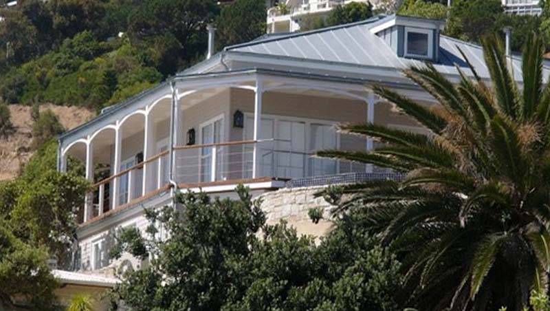

Fortunately, newer technology on wood sealers makes re-applying surface coating easier than older varnishes that had to be completely stripped off before resurfacing.
As in the case of all buildings, the life and efficiency of the constituent materials and the preservative treatments depend upon the quality of the materials and preservatives initially used, their suitability for the climate, and the purpose for which they are used. It is impossible to lay down definite intervals for the maintenance of a timber building. Successful maintenance is best achieved by preventing deterioration. The surface treatment of cladding materials, exposed timbers, beams, frames and other components requires periodic attention and exposed surfaces must be cleaned and retreated as soon as weathering is observed.
Quiz 7 — Services, fire and maintenance
Timber Frame Design and Construction Short Course — Video 2
Trouble playing here? Watch Video 2 on YouTube
Your Course Results
Complete all 7 quizzes above to see your final course score.
No results yet
Your score is calculated from your answers across all seven quizzes.